2017年12月7日星期四

CRP 12X Premium Register & Update

Hardware Requirement:
1. A computer that can access the Internet.
2. A TF card reader/writer and a TF card that need to be updated.
Follow the steps described as below to proceed registration and update:
1. Go to http://mycar.x431.com and click the CReader CRP129 Premium (crp123 premium) once, then click updating icon.

36-1 36-2


2. Download and install the update tool and launch the program when installed.
3. You will be prompted to type in the Serial Number (located at the back of the tool).

36-3

4. After the Serial Number is entered, click [Update] and enter the following information. Click [Submit].

36-4

5. The Register Code can be found by connecting the supplied USB cable to the tool and inserted into the computer.
6. When the tool has powered up, place the cursor on the Help icon and press the [OK] button.

36-5

7. Select [Tool Information], press [OK].

36-6

8. This is the Register Code number for inputting into step 4

36-7

9. Install the TF card from the Launch CReader Professional CRP129 Pro into the supplied USB TF card adapter and insert into USB port of CPU.
10.Reopen the CRP update Suite and select the updates you would like to perform or click [Select All] and click [Download].

36-8 36-9

11. Once all steps are complete, reinsert the TF card into the tool and power the tool via USB in computer or via OBD2 port in vehicle. The tool will prompt you to upgrade, click [OK] to start updating and a progress bar will appear. It may take several minutes to finish update if your upgrade package file is too large, please wait.

36-10
12. The registration process is now complete!

CRP 12X Premium FAQ

Here we list some frequently asked questions and answers relating to Launch CRP129 Premium (crp123 premium).
Question: System halts when reading data stream. What is the reason?
Answer: It may be caused by a slackened connector. Please turn off the CRP12X Premium, firmly connect the connector, and switch it on again.
Question: Screen of main unit flashes at engine ignition start.
Answer: Caused by electromagnetic disturbing, and this is normal phenomenon.
Question: There is no response when communicating with on-board computer.
Answer: Please confirm the proper voltage of power supply and check if the throttle has been closed, the CRP 129P is in the neutral position,and the water is in proper temperature.
Question: Why are there so many fault codes?
Answer: Usually, it’s caused by poor connection or fault circuit grounding.
Warranty
THIS WARRANTY IS EXPRESSLY LIMITED TO PERSONS WHO PURCHASE LAUNCH PRODUCTS FOR PURPOSES OF RESALE OR USE IN THE ORDINARY COURSE OF THE BUYER’S BUSINESS.
LAUNCH electronic product is warranted against defects in materials and workmanship for one year (12 months) from date of delivery to the user.This warranty does not cover any part that has been abused, altered, used for a purpose other than for which it was intended, or used in a manner inconsistent with instructions regarding use. The exclusive remedy for any automotive meter found to be defective is repair or replacement, and LAUNCH shall not be liable for any consequential or incidental damages.
Final determination of defects shall be made by LAUNCH in accordance with procedures established by LAUNCH. No agent, employee, or representative of LAUNCH has any authority to bind LAUNCH to any affirmation, representation, or warranty concerning LAUNCH automotive meters, except as stated herein.

CRP 12X Premium Help

This menu enables you to view Launch CRP129 Premium information and OBD introduction.
In main menu, select [Help] and press [OK] to enter Figure.
35-1
1 DLC Location Information
This option helps you to find the location of the vehicle’s DLC.
2 DTC Library
In Figure 6-1, select [DTC Library] and press [OK] to enter the following screen.
35-2
Press [?]/[?] button to move the highlight bar to different position. Press [ ]/[?] button to alter the value, then press [OK] button, the screen will display definition of the DTC.
3 Abbreviation
This option allows you to view the full name and detailed explanation of the automotive glossary abbreviations.
4 Tool Information
This option displays the related information of your tool.
In Figure 6-1, select [Tool Information] and then press [OK].
35-3
Note: You are strongly recommended to note down the Serial Number and Register Code in Figure 6-3 since these 2 pieces of information are required while registering your LAUNCH Creader CRP129 Premium.
Press [ESC] to return to the previous screen.
5 About OBD
This option allows you to have a general knowledge of OBD.

CRP 12X Premium Diagnose

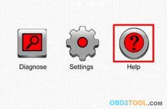
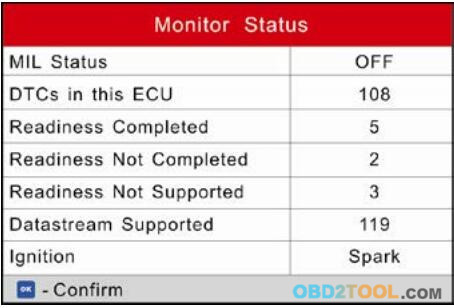
Select [Diagnose] in Main Menu and press [OK], the screen will display Monitor Status interface as following figure
34-1
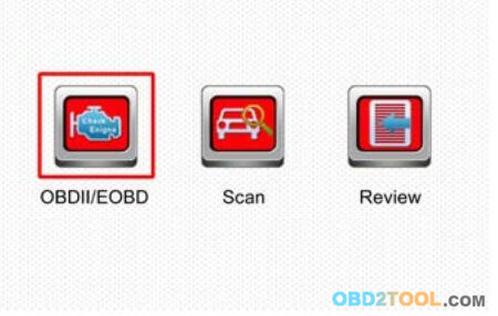
1 OBDII/EOBD Diagnosing
This option presents a quick way to check for DTCs, isolate the cause of the illuminated Malfunction Indicator Lamp (MIL), check monitor status prior to emissions certification testing, verify repairs, and perform a number of other services that are emission-related. In Figure 5-1, press [OK] to enter system, the screen of CRP129 Premium will automatically jump to figure
34-2
Press [OK], a screen similar to Figure as follow will appear:
34-3
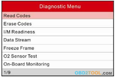
It mainly includes the following functions:
1. Read Codes
This option is used to identify which section of the emission control system has malfunctioned.
2. Erase Codes
After reading the retrieved codes from the vehicle and certain repairs have been carried out, you can use this function to erase the codes from the vehicle. Before performing this function, please be sure the vehicle’s ignition key is in the ON position with the engine off.
Notes:
a. Before performing this function, make sure to retrieve and record the trouble codes.
b. After clearing, you should retrieve trouble codes once more or turn ignition on and retrieve codes again. If there are still some trouble codes in the system,please troubleshoot the code using a factory diagnosis guide, then clear the code and recheck.
3. I/M Readiness
I/M refers to Inspection and Maintenance that is legislated by the Government to meet federal clean-air standards. I/M Readiness indicates whether or not the various emissions-related systems on the vehicle are operating properly and are ready for Inspection and Maintenance testing.
The purpose of the I/M Readiness Monitor Status is to indicate which of the vehicle’s Monitors have run and completed their diagnosis and testing(as described in Chapter 2.5), and which ones have not yet run and completed testing and diagnosis of their designated sections of the vehicle’s emissions system.
The I/M Readiness Monitor Status function also can be used (after repair of a fault has been performed) to confirm that the repair has been performed correctly, and/or to check for Monitor Run Status.
4. Data Stream
This option retrieves and displays live data and parameters from the vehicle’s ECU.
5. View Freeze Frame
When an emission-related fault occurs, certain vehicle conditions are recorded by the on-board computer. This OBD2 Code Reader Scanner is referred to as freeze frame data. Freeze Data is a snapshot of the operating conditions at the time of an emission-related fault.
Note: If DTCs were erased, Freeze Data may not be stored in vehicle memory depending on vehicle.
6. O2 sensor test
The results of O2 sensor test are not live values but instead the results of the ECU’s last O2 sensor test. For live O2 sensor readings, refer to any of the live sensor screens such as Graph Screen.
Not all test values are applicable to all vehicles. Therefore, the list generated will vary depending on vehicle. In addition, not all vehicles support the Oxygen Sensors screen.
7. On-board monitor test
This function can be utilized to read the results of on-board diagnostic monitoring tests for specific components/systems.
8. EVAP System Test
The EVAP test function lets you initiate a leak test for the vehicle’s EVAP system. The LAUNCH CRP129 Premium Scanner does not perform the leak test, but signals to vehicle’s on-board computer to initiate the test. Before using the system test function, refer to the vehicle’s service repair manual to determine the procedures necessary to stop the test.
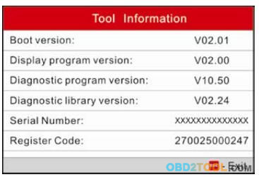
9. Vehicle Info
This option displays the vehicle information, such as VIN (Vehicle identification Number), CID (Calibration ID) and CVN (Calibration Verification Number).
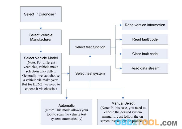
5.2 System Diagnosing
This function is specially designed to diagnose electronic control system of single vehicle model which includes the following systems:
● ENG (Engine)
● ABS (Anti-lock Brake System)
● TCM (Transmission Control Module)
● SRS (Supplemental Restraint System)
Notes:
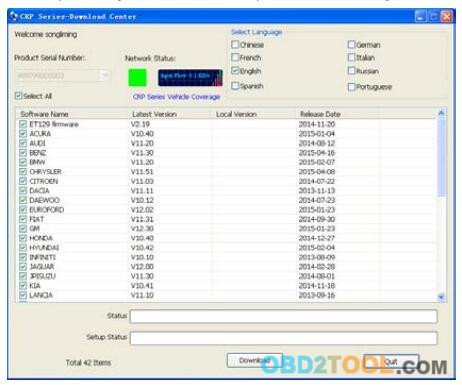
● Before diagnosing, please make sure the diagnostic program corresponding to certain vehicle model has been installed on your CRP12X Premium.
● For vehicles manufactured by different vendors, it is possible that it has different diagnostic menus. Refer to the flowchart illustrated as below to diagnose a vehicle:
34-4
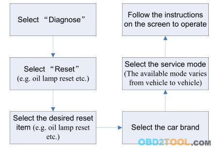
5.3 Resetting (Only applies to CRP129 Premium)
In addition to amazing & powerful diagnostic function, Code Reader Scanner CRP129P also features Oil / Service lamp reset. There are two methods to reset service lamp: Manual reset or Auto reset. Auto reset follows the principle of sending command from CRP129 Premium to vehicle’s ECU to do resetting. While using manual reset, users just follow the on-screen instructions to select appropriate execution options, enter correct data or values, and perform necessary actions, the system will guide you through the complete performance for various service operations.
Follow the flowchart shown as below to perform resetting.
34-5
5.4 Review
This function is used to review or delete the recorded DTC, Data Streams and Freeze Frame.

CRP 12 X Premium Connection

1 Install TF card
1) Take out the TF card from package box.
2) Insert the TF card into the CRP129 Premium (CRP123 Premium) TF card slot perpendicularly. Make sure is fully inserted in the right place with the “micro” label facing upward.
Note: You can hear a clicking sound if you insert the TF card in the right place. Press the card slightly, it will be ejected automatically.
2 Connect CRP12X Premium
1). Turn the ignition off.
2). Locate vehicle’s DLC socket: It provides standard 16 pins and is generally located on driver’s side, about 12 inches away from the center of dashboard. See Figure 2-2. If DLC is not equipped under dashboard, a label indicating its position will be given. In case no DLC is found, please refer to Automobile Repair Manual.
3). Plug one end of the diagnostic cable into the OBD II 16 pin connector of CRP12X Premium, and connect the other end to the vehicle’s DLC.
33-1
4). Turn the ignition on. Engine can be off or running.
5). After finishing, the system will start initializing. After initialization, the system will enter the main menu interface.
CAUTION: Don’t connect or disconnect any test equipment with ignition on or engine running.
3 Settings
Select [Settings] in the main menu and press [OK], the system will enter the following screen:
33-2
1) Language
This option enables you to set the user interface language.
Note: Due to continuous software upgrade, language interface may differ from different software versions.
2) Unit of Measure
This option allows you to set measurement OBD2 Code Reader Scanner.
3) Beeper
It is used to set On/Off the buzzer.
4) Record Mode
It is used to turn On/Off recording function.

CRP 12 X Premium Product Descriptions

1 Outline of CRP12X Premium
32-1
Note:  CRP123 Premium(CRP129 Premium) Series feature same appearance. Here we only take Launch CRP129 Premium for example.
32-2
2 Specifications
● Screen: 4.0” TFT LCD display
● Input voltage range: 9~18V
● Working temperature: 0 to 50°C (32 to 122 F°)
● Storage temperature: – 20 to 70°C (-4 to 158 F°)
● External Dimension: 7.7”(L) x 4.17”(W) x 1.25”(H)
● Weight: <400g
3 Accessories Included
1. CRP12X Premium handset
2. Diagnostic cable
3. User manual
4. TF card
5. TF card reader
6. USB cable

CRP12X Premium Introduction And General Information

31-1
1. Introduction
The CRP123 Premium(CRP129 PREMIUM) Series are specially developed by LAUNCH, which supports all 10 modes of OBD II test for a complete diagnosis. Featuring the 3.5" TFT color display, it enables users to read/dear DTCs, record, save and playback data in live graphic display. The CRP129 Premium (CRP123 PREMIUM) Series are also very easy to use. With built-in help menus and code definitions, diagnosing and repairing that dreaded Check Engine Light is now easier than ever!
Moreover, CRP12X Premium Series also feature the following bi-directional “special tests": EVAP, 02 Sensor, I/M Readiness, MIL Status, VIN Info, and On-board monitors testing.
It can be connected to PC through the USB cable for upgrade to keep updated with the latest software version.
Note: CRP129 Premium (CRP123 Premium) Series may automatically reset while being disturbed by strong static electricity. THIS IS A NORMAL REACTION.
2. General Information
2.1 On-Board Diagnostics (OBD) II
The first generation of On-Board Diagnostics (OBD I) was developed by the California Air Resources Board (ARB) and implemented in 1988 to monitor some of the emission control components on vehicles. As technology evolved and the desire to improve the On-Board Diagnostic system increased, a new generation of On-Board Diagnostic system was developed. This second generation of On-Board Diagnostic regulations is called “OBD If.
The OBD2 Scanner is designed to monitor emission control systems and key engine components by performing either continuous or periodic tests of specific components and vehicle conditions. When a problem is detected, the OBD II system turns on a warning lamp (MIL) on the vehicle instrument panel to alert the driver typically by the phrase of “Check Engine" or "Service Engine Soon". The system will also store important information about the detected malfunction so that a technician can accurately find and fix the problem. Here below follow three pieces of such valuable information:
1)Whether the Malfunction Indicator Light (MIL) is commanded ‘on’ or ‘off;
2)Which, if any, Diagnostic Trouble Codes (DTCs) are stored;
3)Readiness Monitor status.
2.2 Diagnostic Trouble Codes (DTCs)
OBD2 Code Reader are codes that are stored by the on-board computer diagnostic system in response to a problem found in the vehicle. These codes identify a particular problem area and are intended to provide you with a guide as to where a fault might be occurring within a vehicle. OBD II Diagnostic Trouble Codes consist of a five-digit alphanumeric code. The first character, a letter, identifies which control system sets the code. The second character, a number, 0-3; other three characters, a hex character, 0-9 or A-F provide additional information on where the DTC originated and the operating conditions that caused it to set. Here below is an example to illustrate the structure of the digits:
31-2
2.3 Location of the Data Link Connector (DLC)
The DLC (Data Link Connector or Diagnostic Link Connector) is typically a 16-pin connector where diagnostic code readers interface with the vehicle’s on-board computer. The DLC is usually located 12 inches from the center of the instrument panel (dash), under or around the driver’s side for most vehicles. If Data Link Connector is not located under dashboard, a label should be there telling location. For some Asian and European vehicles, the DLC is located behind the ashtray and the ashtray must be removed to access the connector. If the DLC cannot be found,refer to the vehicle’s service manual for the location.
31-3
2.4 OBD II Readiness Monitors
An important part of a vehicle’s OBD II system is the Readiness Monitors, which are indicators used to find out if all of the emissions components have been evaluated by the OBD II system. They are running periodic tests on specific systems and components to ensure that they are performing within allowable limits.
Currently, there are eleven OBD II Readiness Monitors (or I/M Monitors) defined by the U.S. Environmental Protection Agency (EPA). Not all monitors are supported in every vehicles and the exact number of monitors in any vehicle depends on the motor vehicle manufacturer’s emissions control strategy.
Continuous Monitors — Some of the vehicle components or systems are continuously tested by the vehicle’s OBD II system, while others are tested only under specific vehicle operating conditions. The continuously monitored components listed below are always ready:
1. Misfire
2. Fuel System
3. Comprehensive Components (CCM)
Once the vehicle is running, the OBD II system is continuously checking the above components, monitoring key engine sensors, watching for engine misfire, and monitoring fuel demands.
Non-Continuous Monitors — Unlike the continuous monitors, many emissions and engine system components require the vehicle to be operated under specific conditions before the monitor is ready. These monitors are termed non-continuous monitors and are listed below:
1) EGR System
2) O2 Sensors
3) Catalyst
4) Evaporative System
5) O2 Sensor Heater
6) Secondary air Injection
7) Heated Catalyst
8) A/C system
2.5 OBD II Monitor Readiness Status
OBD II systems must indicate whether or not the vehicle’s PCM’s monitor system has completed testing on each component. Components that have been tested will be reported as “Ready”, or “Complete”, meaning they have been tested by the OBD II system. The purpose of recording readiness status is to allow inspectors to determine if the vehicle’s OBD II system has tested all the components and/or systems.
The Powertrain Control Module (PCM) sets a monitor to “Ready” or “Complete” after an appropriate drive cycle has been performed. The drive cycle that enables a monitor and sets readiness codes to “Ready” varies for each individual monitor. Once a monitor is set as “Ready” or “Complete”, it will remain in this state. A number of factors, including erasing of Diagnostic Trouble Codes (DTCs) with a code reader or a disconnected battery, can result in Readiness Monitors being set to “Not Ready”. Since the three continuous monitors are constantly evaluating,
they will be reported as “Ready” all of the time. If testing of a particular supported non-continuous monitor has not been completed, the monitor status will be reported as “Not Complete” or “Not Ready.”
In order for the OBD monitor system to become ready, the vehicle should be driven under a variety of normal operating conditions. These operating conditions may include a mix of highway driving and stop and go, city type driving, and at least one overnight-off period. For specific information on getting your vehicle’s OBD monitor system ready, please consult your vehicle owner’s manual.